Introduction
Spaghetti Badge is a 3-star challenge at the FCSC. Here is the statement:
1Mr. Spaghetti designed a rather unique light-up badge... let's just say he didn't wire the LEDs in the most optimal way. This badge features a 120x24 WS2812B LED matrix that displays a flag. The microcontroller controlling the LED matrix is a WCH CH32V003F4U6.
2
3The PCB fabrication data for this badge and its firmware are available. Will you be able to figure out this flag?
4
5Note: The order of the copper layers follows the standard convention, i.e., F.Cu, In1.Cu, In2.Cu, In3.Cu, In4.Cu, and then B.Cu. The silkscreen Gerber file is not provided; it is up to you to determine the placement and orientation of the components.
We are provided with files in Gerber format and the firmware of the microcontroller.
Visualizing the board
The first step I decided to take was to visualize the board to understand what I would be working with. I looked at some tools online and decided to go with KiCad (it was also the software used to generate the challenge, with %TF.GenerationSoftware,KiCad,Pcbnew,9.0.6*% in the header, so I thought it could be a great idea).
So, after importing the Gerber file, I needed to wait while my computer decided it was now a helicopter.

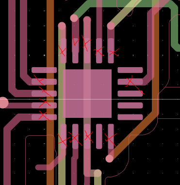
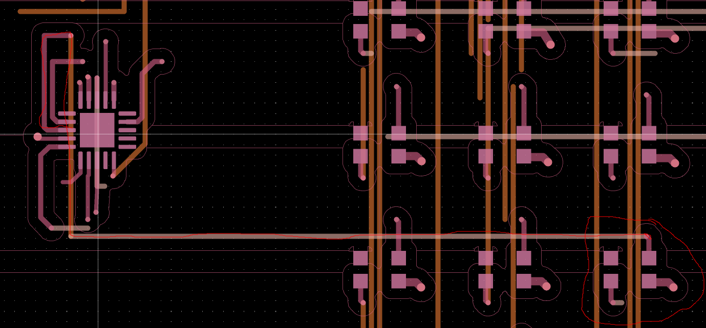
First look at the file:
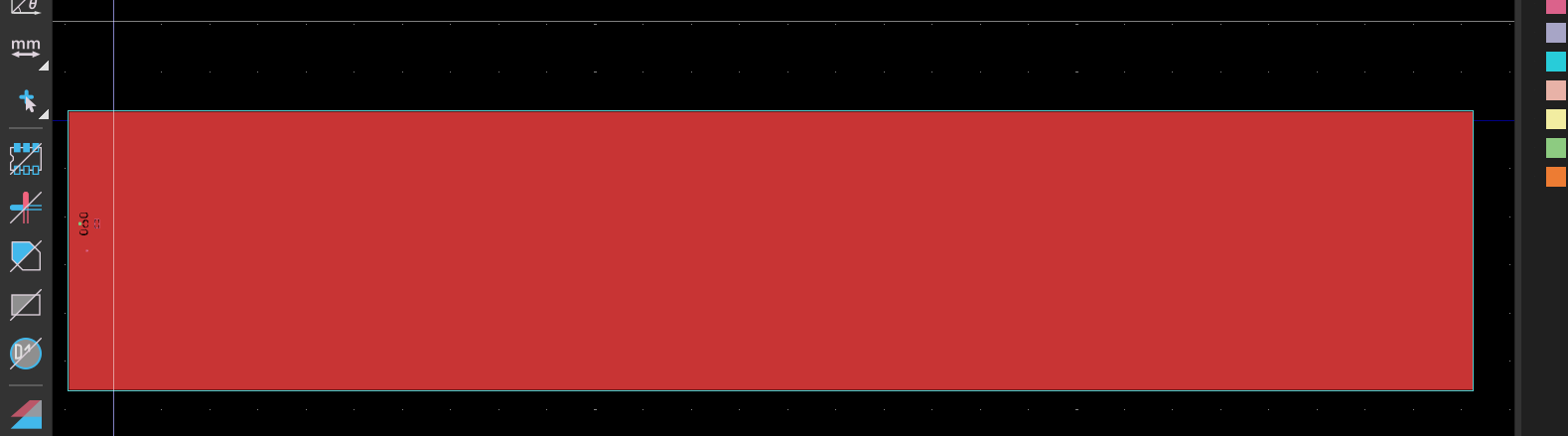
Nice, it’s red. After playing with the different options, I managed to get a good view of the system.
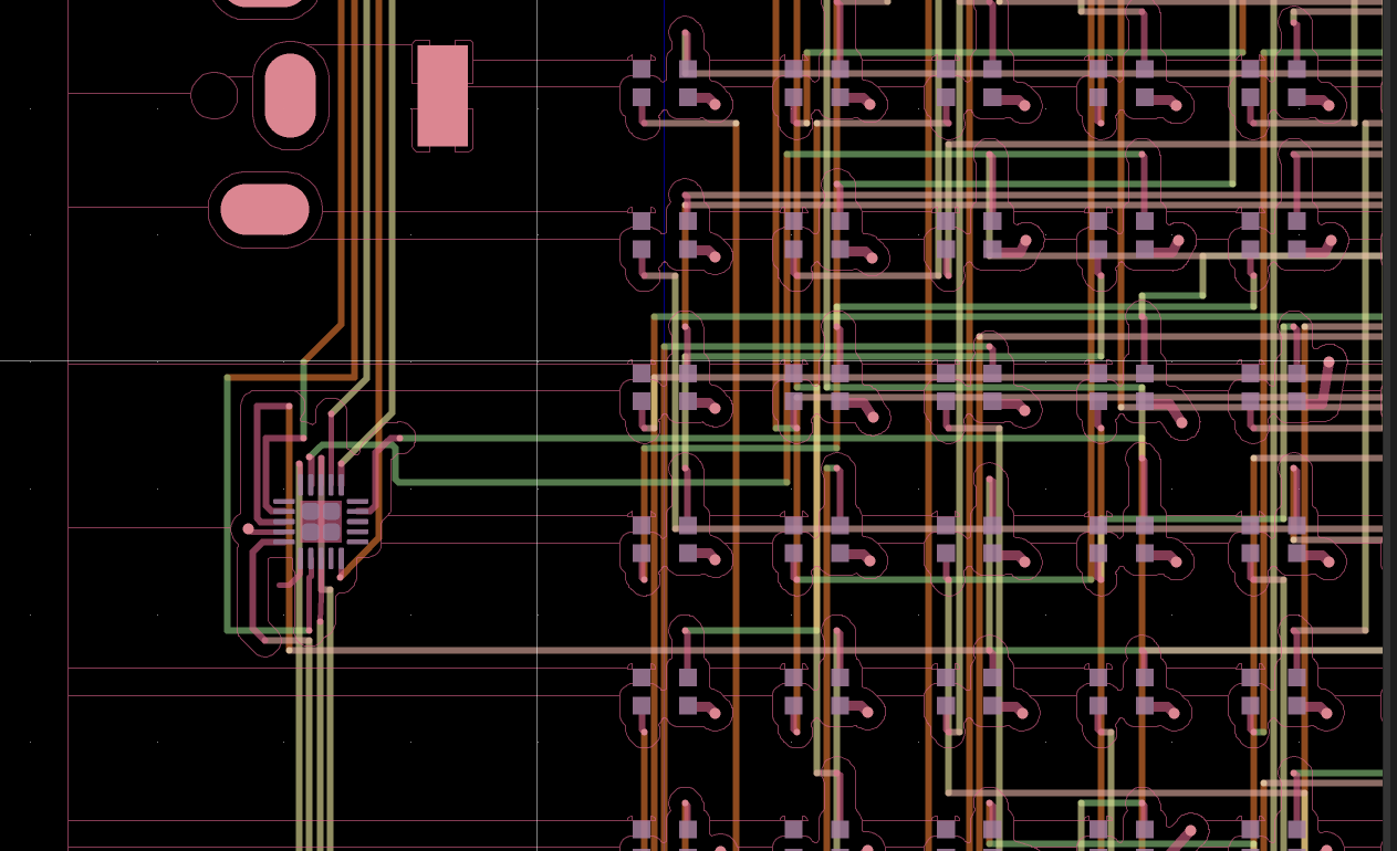
On the board, there is the microcontroller on the left and then all the LEDs. Now that I knew what I would be working with and had seen the spaghetti nightmare waiting for me, I decided to move on and look at the different standards for both the LEDs and the microcontroller.
The standards
It was easy to find good documentation about both the LEDs and the microcontroller (yes, I’m thinking about you, WAPI), so this was nice!
The LED
Here is the datasheet
There are 2880 WS2812B LEDs on the board. Here is the schema:
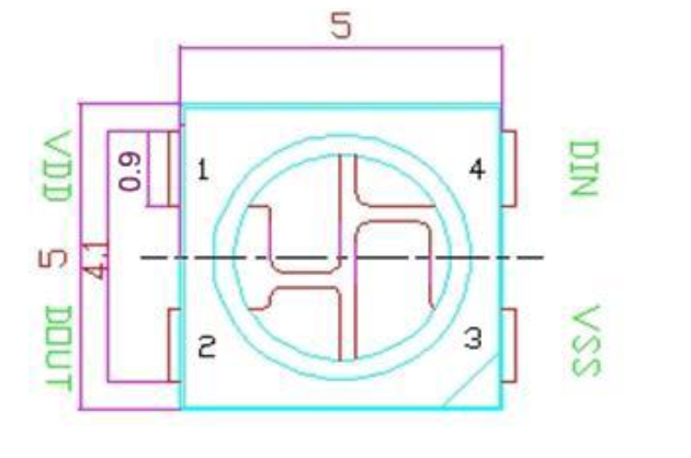
There are 4 pins:
- VDD: Power supply
- DOUT: Control data signal output
- VSS: Ground
- DIN: Control data signal input
The way those LEDs work is pretty straightforward: Some data goes through the first LED on the DIN pin in blocks of 24 bits containing the RGB data (it is sent in GRB order and MSB first, so the highest bit is sent first). The first LED will consume its 24 bits and send the remaining data through the DOUT pin.
So the hard part will be to find what data is sent and where it goes next, because, as we can see on the board, it will not be easy.
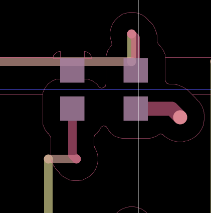
Here is a close-up look at an LED without wires everywhere. Since we don’t have the orientation, I can only guess that either the top-right pin is the DIN or DOUT, and the bottom-left pin is the other one.
So that will be all for now about the board. Now we need to find what data is sent and how it is sent to them.
The microcontroller
Here is the datasheet
Here, the F4U6 model suffix is used. It means that:
- F = 20 pins
- 4 = 16 Kbytes of Flash memory
- U = QFN package
- 6 = The temperature range is between -40° and 85° Great!!! Is it useful? ……………… meh
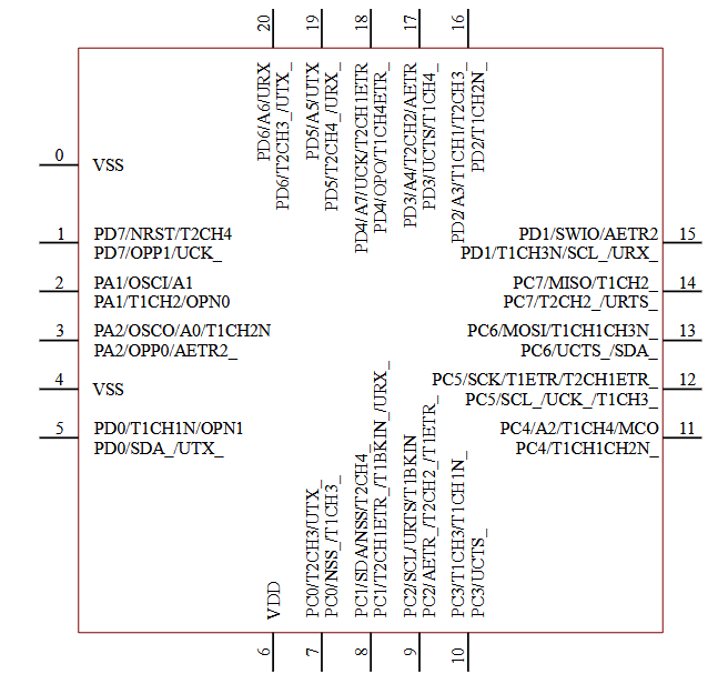
For useful info, here is the layout of the chip and pin arrangement:
On KiCad, there is the corresponding schema.
It is possible to see that:
- on the left side, PA1, PA2, and PD0 are used for data
- on the bottom, PC0, PC1, and PC3
- on the right, PC7
- on the top, PD2, PD3, PD4, PD5, and PD6
So there are 12 data channels, and the data is sent from there to the LEDs and then chained through all of them.
The reverse
Now that I have all this information, I need to move on to the reversing part.
First thing first, file and strings on the file:
file spaghetti-badge.bin
spaghetti-badge.bin: data

strings spaghetti-badge.bin
]Ech
*s% 4cD
uVck
U0su
@LA7
EPA1
@}cP
@rD"
`rcP
@2D"
7TUU
7433
WUU3d
G3us
7WUUM
2G"Fc
2G"F
UREc
UUU3
7733
UUU3
7VUU
7733
UUUU
7633
7VUU
        https://youtu.be/1nWNXO3CZkU
DG$`
@@,(
LhI
Mhhhhh wait let me light up my candle:

Much better, so I clicked anyway and it is the Spaghetti scene from ‘Lady and the Tramp’, so cute, but we need to flag.
Let’s open Ghidra.
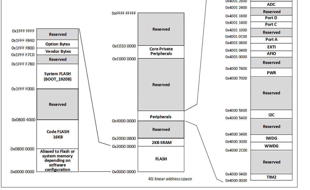
This file is not recognized, so I need to specify the instruction set, which is RISC-V. Looking at the memory layout, the base address of the code flash is 0X0800 0000. I can set that as the base address of the binary in Ghidra and the 2 KB SRAM memory map from an offset of 0X2000 0000 of the code flash with a length of 0x800.
Initialization
The first instruction being a jump, let’s see what happens at 0x08000348.
At the beginning of the code, there is a loop copying data:
 1
 2void FUN_ram_08000348(void)
 3
 4{
 5  undefined4 *puVar1;
 6  undefined4 *puVar2;
 7
 8  gp = 0x28000b44;
 9  puVar1 = &DAT_ram_08000004;
10  puVar2 = (undefined4 *)&DAT_ram_28000000;
11  do {
12    *puVar2 = *puVar1;
13    puVar1 = puVar1 + 1;
14    puVar2 = puVar2 + 1;
15  } while (puVar2 < &DAT_ram_28000344);
The data from:
0x08000004 -> 0x8000348
is copied to:
0x28000000 -> 0x28000344
The data from:
0x0800228c -> 0x8002290
is copied to:
0x28000344 -> 0x28000348
And
0x28000348 -> 0x28000464
is nulled to \x00.
Then function FUN_ram_0800041a is called.
Sending the data
At the end of the function, we can see 12 similar loops. Well well well, interesting…
![]()
After I had a closer look, it first takes a pointer to the memory and loops 30 times, and for each byte a function is called 8 times with a bit shift on the data, so once for each bit of the byte.
Doing some quick math: 30 bytes, 8 calls of the function, 12 times, so 12 _ (30 _ 8) => 12 * 240, which is exactly the number of pixels on the board, so it’s perfect.
The function is called with 2 parameters:
- A different number each time, but either it is
16 * 1 + x,16 * 4 + x, or16 * 6 + x, so there are 3 “different” numbers - One of the bits that is masked with uVar3, either sending 0 or uVar3 as a parameter.
But now let’s dive deeper.
We can’t go to the function because the memory at 0X2800 0000 is empty and filled at runtime by being copied from 0x0800 0004, so the function is actually at 0x0800 002CA. Ghidra just saw that as a bunch of bytes, but decompiling it and labeling it as a function reveals its mystery.
The function loops 24 times and copies the parameter to 0x4001 0810 + iVar3.
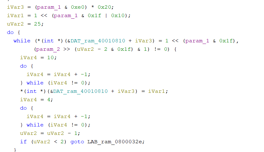
The prefix 0x4 of the address didn’t ring a bell directly, but the 24 bits did: it is most probably the GRB data. And after going back to the memory layout, I saw that 0x4000 0000 corresponds to the peripherals memory area. More precisely, 0x4001 0800 is Port A. But it is copied to this address with an offset.
Okay, a lot is going on, so a little recap:
The microcontroller is sending data through 12 different pins to the LEDs, which receive it from one end, consume 24 bits to light up with the right color, and channel the rest of the data to the next LED, and so on.
I found that a big block of data is read and sent to 12 peripherals, so those are the LED colors, but now I need to know which loop corresponds to which pin.
Looking at how iVar3 is computed, it’s a mask and then a multiplication.
When the function is called with param1 = 1, iVar3 is 0; with param1 = 0x63, iVar3 = 0xc00.
In those two cases, the function is either writing to0x4001 0810 or 0x4001 1410.
Looking at the layout of the memory:
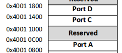
It is somewhere in Port A and somewhere in Port D.
The function is called with 12 different parameters, and they are: 0x0{1,2}/0x4{0,1,3,7}/0x6{0,2,3,4,5,6}.
With a bit of guessing, 0x47, for example, is probably corresponding to Port C7, and 0x62 is Port D2.
The data that is sent is read from 0x20EC to 0x2254, that is 2880 bits of data, one for each pixel. The next step is to take that data and see the cascading process to light the correct LEDs. At that point, I still don’t know how I will manage the spaghetti part, so good luck, future me.
The spaghettis
With a little script, we can retrieve the data that is sent to each pin:
 1PA1 = ""
 2PA2 = ""
 3PC0 = ""
 4PC1 = ""
 5PC3 = ""
 6PC7 = ""
 7PD0 = ""
 8PD2 = ""
 9PD3 = ""
10PD4 = ""
11PD5 = ""
12PD6 = ""
13
14with open("spaghetti-badge.bin", "rb") as f:
15    data = f.read()
16    nb = 0
17
18    for i in range(0x20EC, 0x2254):
19        byte = data[i]
20        binary = bin(byte)[2:].zfill(8)
21
22        loop_index = nb // 30
23        nb += 1
24        match loop_index:
25            case 0:
26                PA1 += binary
27            case 1:
28                PD3 += binary
29            case 2:
30                PC0 += binary
31            case 3:
32                PD2 += binary
33            case 4:
34                PC3 += binary
35            case 5:
36                PD5 += binary
37            case 6:
38                PA2 += binary
39            case 7:
40                PC1 += binary
41            case 8:
42                PD6 += binary
43            case 9:
44                PC7 += binary
45            case 10:
46                PD4 += binary
47            case 11:
48                PD0 += binary
49            case _:
50                raise Exception("WTF")
51
52print(f"PA1: {PA1}")
53print(f"light 0 on PA1 will be: {"on" if PA1[0] == "1" else "off"}")
Okay, now we need to find on the PCB which index corresponds to which light,
because for example:
This corresponds to the first value of PA1, so it will be on. The LED will consume its color and send the rest to the next LED, which will do the same, and so on. For a moment, I was sincerely thinking about doing this by hand. At the speed of, let’s say, 3 LEDs/minute, it would take me 16 hours. Instead, let’s spend 20 minutes understanding how to automate this for the next time I have to do it. (It wasn’t actually that long.)
I tried to find different methods:
- The KiCad PCB editor was one of them, but I never managed to launch it, as it systematically crashed.
- I remember having a little voice saying OCR in my head, but at this point, let’s do it by hand.
- A Python library to parse the file and after that, I don’t know, do the cascading process or something like this, but in the future.
After brainstorming, I realized I didn’t even know the format of the file or how it was composed, and I thought that it could be useful to know.
I started with the first layer, so F_Cu. There were a lot of positions in the format X.....Y.......
I removed all those lines to understand the data better.
After some time, I decided to try and read the Gerber file by hand to see if there was some useful data, and there was. Starting with the first layer, F.Cu, I decided to sanitize all the lines specifying a position, so the X.....Y..... ones.
The data for one pin looks like this:
%TD*%
%TO.P,D1850,1*%
%TO.N,+5V*%
X275085000Y-101450000D03*
%TO.P,D1850,2*%
%TO.N,Net-(D1850-DOUT)*%
X275085000Y-102550000D03*
%TO.P,D1850,3*%
%TO.N,GND*%
X276915000Y-102550000D03*
%TO.P,D1850,4*%
%TO.N,Net-(D1849-DOUT)*%
X276915000Y-101450000D03*
Here, it’s for LED D1850. There is the position of each pin and some more information. The 1 corresponds to VDD; it is possible to confirm this with the +5V below, the 2 is DOUT, and so on.
It’s the same as the LED schema in the datasheet.
The important information is that LED 1850 receives data from LED 1849, and we have the position of the LED.
At this point, I realized it wouldn’t be as hard as I first imagined. I need to retrieve the LEDs and their positions, and the origin of the data. Talking about the origin, how is the data coming from the microcontroller?
I wanted to look at D0, but it doesn’t exist. Maybe it was all a lie and we start counting at 1 in reality? I don’t know, but by going back to D1, here is the data:
%TO.P,D1,2*%
%TO.N,Net-(D1-DOUT)*%
%TO.P,D1,4*%
%TO.N,/L0*%
So D1 gets the data from… /L0??
After looking again inside the file, there are the D-X components and U1, with the same data format, so a pin number and a value with /LX.
It goes like this:
- 2 (PA1) -> L0
- 3 (PA2) -> L6
- 5 (PD0) -> L11
- 7 (PC0) -> L2
- 8 (PC1) -> L7
- 10 (PC3) -> L4
- 14 (PC7) -> L9
- 16 (PD2) -> L3
- 17 (PD3) -> L1
- 18 (PD4) -> L10
- 19 (PD5) -> L5
- 20 (PD6) -> L8 The correspondence between the number and the pin name can be done with the datasheet.
And, for example, something like this can be constructed:
PD0 (L11) -> D2641
It is possible to verify this information is correct because, after following the path on KiCad and looking at the position of D2641 DIN, it is the same as in the file.
TO.P,D2641,4*%
%TO.N,/L11*%
X24915000Y-131450000D03*
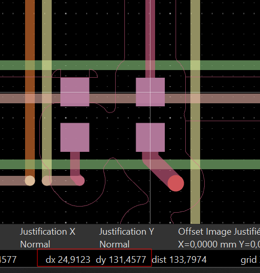
The information that will make my life easier is that LED n will provide data to LED n+1, and one pin will send data to 240 LEDs, so L0 will send the data to LEDs 1-240 and L1 to 241-480…
And so on. So now I need to get the position of those LEDs.
I wrote a little parser in Python to retrieve the position of one pin, for example DOUT, and then sort them by Y then X coordinates to get the layout of all the LEDs in order. Then I can loop through the previous data gathered to turn on each LED. We can loop in order from L0 to L11 and light the LEDs from index index * 240 to (index + 1) * 240 - 1.
 1
 2for i in range(len(PA1)):
 3    ALL_LEDS[i + 1] = (ALL_LEDS[i + 1][0], ALL_LEDS[i + 1][1], PA1[i] == "1")
 4
 5for i in range(len(PD3)):
 6    ALL_LEDS[i + 241] = (ALL_LEDS[i + 241][0], ALL_LEDS[i + 241][1], PD3[i] == "1")
 7
 8for i in range(len(PC0)):
 9    ALL_LEDS[i + 481] = (ALL_LEDS[i + 481][0], ALL_LEDS[i + 481][1], PC0[i] == "1")
10
11for i in range(len(PD2)):
12    ALL_LEDS[i + 721] = (ALL_LEDS[i + 721][0], ALL_LEDS[i + 721][1], PD2[i] == "1")
13
14for i in range(len(PC3)):
15    ALL_LEDS[i + 961] = (ALL_LEDS[i + 961][0], ALL_LEDS[i + 961][1], PC3[i] == "1")
16
17for i in range(len(PD5)):
18    ALL_LEDS[i + 1201] = (ALL_LEDS[i + 1201][0], ALL_LEDS[i + 1201][1], PD5[i] == "1")
19
20for i in range(len(PA2)):
21    ALL_LEDS[i + 1441] = (ALL_LEDS[i + 1441][0], ALL_LEDS[i + 1441][1], PA2[i] == "1")
22
23for i in range(len(PC1)):
24    ALL_LEDS[i + 1681] = (ALL_LEDS[i + 1681][0], ALL_LEDS[i + 1681][1], PC1[i] == "1")
25
26for i in range(len(PD6)):
27    ALL_LEDS[i + 1921] = (ALL_LEDS[i + 1921][0], ALL_LEDS[i + 1921][1], PD6[i] == "1")
28
29for i in range(len(PC7)):
30    ALL_LEDS[i + 2161] = (ALL_LEDS[i + 2161][0], ALL_LEDS[i + 2161][1], PC7[i] == "1")
31
32for i in range(len(PD4)):
33    ALL_LEDS[i + 2401] = (ALL_LEDS[i + 2401][0], ALL_LEDS[i + 2401][1], PD4[i] == "1")
34
35for i in range(len(PD0)):
36    ALL_LEDS[i + 2641] = (ALL_LEDS[i + 2641][0], ALL_LEDS[i + 2641][1], PD0[i] == "1")

Not the best code I wrote, but it works, right? I first verified that the extraction was correct. I compared it with the layout, the positions, and everything else. I had the right numbers each time, I triple-checked, and it seemed good to me, so let’s roll and launch the code:
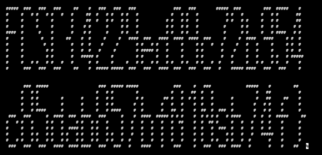
 …
…
……..
It does look like something, but I can’t read anything, so panic mode on, because in hardware with something like this, either I am very close or I need to start everything again. First try (I started to panic because it looked almost good, but in hardware it could either mean that you are close or that you need to start everything again).
But then I found out that in my loop printing the LEDs, I was doing this:
1print("#" if leds_sorted[i][1][2] else " ", end=" ")
so printing a space in every case.
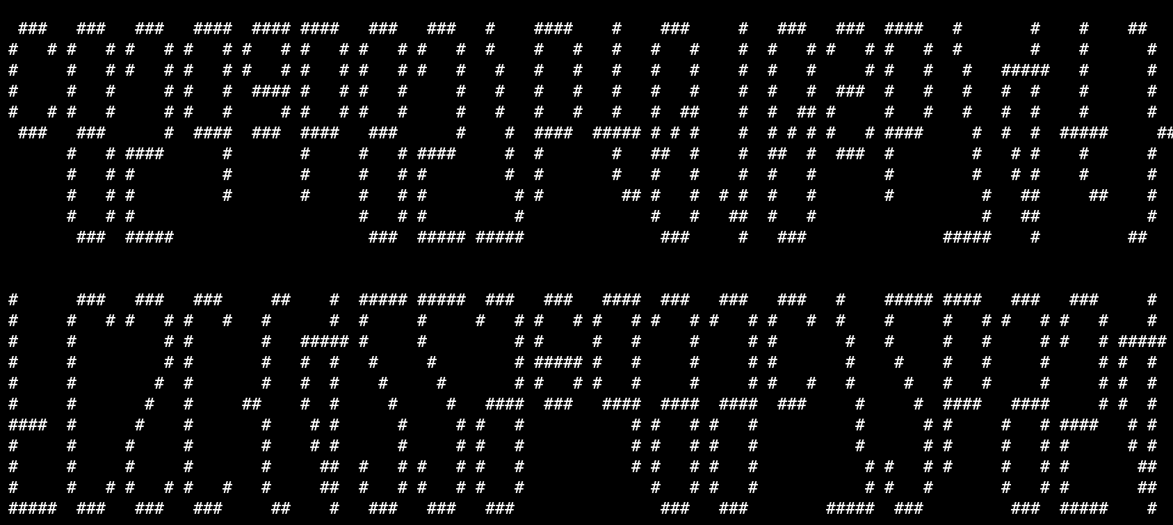
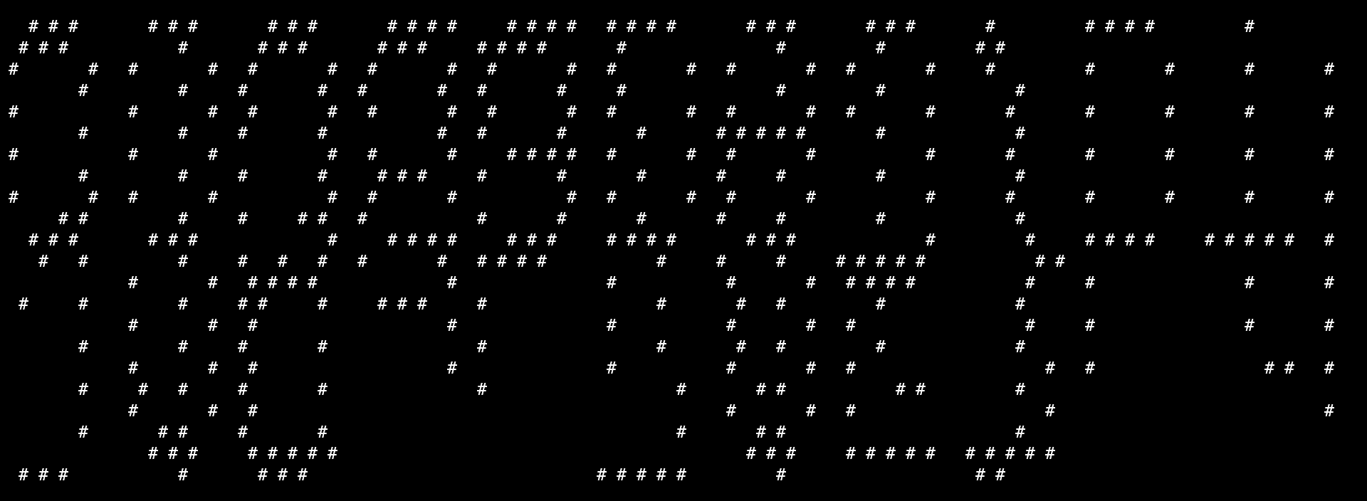
That moment when FLAG:

Now I know that I have the flag, but it’s hard to turn my head or take a screenshot and reverse it, so let’s fix it in the code.
The order of the Y coordinates was reversed, so just add a - before it to get the flag.
YOUHOUUUU
Here is the final code I used to print the flag:
  1import re
  2
  3DATA = []
  4
  5PA1 = ""
  6PA2 = ""
  7PC0 = ""
  8PC1 = ""
  9PC3 = ""
 10PC7 = ""
 11PD0 = ""
 12PD2 = ""
 13PD3 = ""
 14PD4 = ""
 15PD5 = ""
 16PD6 = ""
 17
 18
 19with open("spaghetti-badge.bin", "rb") as f:
 20    data = f.read()
 21
 22    nb = 0
 23    for i in range(0x20EC, 0x2254):
 24
 25        byte = data[i]
 26        binary = bin(byte)[2:].zfill(8)
 27        loop_index = nb // 30
 28        nb += 1
 29        match loop_index:
 30            case 0:
 31                PA1 += binary
 32            case 1:
 33                PD3 += binary
 34            case 2:
 35                PC0 += binary
 36            case 3:
 37                PD2 += binary
 38            case 4:
 39                PC3 += binary
 40            case 5:
 41                PD5 += binary
 42            case 6:
 43                PA2 += binary
 44            case 7:
 45                PC1 += binary
 46            case 8:
 47                PD6 += binary
 48            case 9:
 49                PC7 += binary
 50            case 10:
 51                PD4 += binary
 52            case 11:
 53                PD0 += binary
 54            case _:
 55                print(f"Unknown loop index: {loop_index}")
 56                raise Exception("WTF")
 57
 58
 59# print(f"PA1: {PA1}")
 60# print(f"light 0 on PA1 will be: {"on" if PA1[0] == "1" else "off"}")
 61
 62
 63ALL_LEDS = {}
 64
 65
 66with open("gerber/pcb-F_Cu.gbr", "r") as f:
 67    prev_line = ""
 68    for line in f:
 69
 70        if re.match(r"%TO\.P,D\d+,2\*%", line) and prev_line.startswith("X"):
 71            led_number = int(line.split(",")[1][1:])
 72            x_coord = int(prev_line.split("Y")[0][1:]) / 100
 73            y_coord = int(prev_line.split("Y")[1].split("D")[0]) / 100
 74            ALL_LEDS[led_number] = (x_coord, y_coord, False)
 75        prev_line = line
 76# print(ALL_LEDS)
 77
 78NB = 0
 79
 80for i in range(len(PA1)):
 81    ALL_LEDS[i + 1] = (ALL_LEDS[i + 1][0], ALL_LEDS[i + 1][1], PA1[i] == "1")
 82for i in range(len(PD3)):
 83    ALL_LEDS[i + 241] = (ALL_LEDS[i + 241][0], ALL_LEDS[i + 241][1], PD3[i] == "1")
 84for i in range(len(PC0)):
 85    ALL_LEDS[i + 481] = (ALL_LEDS[i + 481][0], ALL_LEDS[i + 481][1], PC0[i] == "1")
 86for i in range(len(PD2)):
 87    ALL_LEDS[i + 721] = (ALL_LEDS[i + 721][0], ALL_LEDS[i + 721][1], PD2[i] == "1")
 88for i in range(len(PC3)):
 89    ALL_LEDS[i + 961] = (ALL_LEDS[i + 961][0], ALL_LEDS[i + 961][1], PC3[i] == "1")
 90for i in range(len(PD5)):
 91    ALL_LEDS[i + 1201] = (ALL_LEDS[i + 1201][0], ALL_LEDS[i + 1201][1], PD5[i] == "1")
 92for i in range(len(PA2)):
 93    ALL_LEDS[i + 1441] = (ALL_LEDS[i + 1441][0], ALL_LEDS[i + 1441][1], PA2[i] == "1")
 94for i in range(len(PC1)):
 95    ALL_LEDS[i + 1681] = (ALL_LEDS[i + 1681][0], ALL_LEDS[i + 1681][1], PC1[i] == "1")
 96for i in range(len(PD6)):
 97    ALL_LEDS[i + 1921] = (ALL_LEDS[i + 1921][0], ALL_LEDS[i + 1921][1], PD6[i] == "1")
 98for i in range(len(PC7)):
 99    ALL_LEDS[i + 2161] = (ALL_LEDS[i + 2161][0], ALL_LEDS[i + 2161][1], PC7[i] == "1")
100for i in range(len(PD4)):
101    ALL_LEDS[i + 2401] = (ALL_LEDS[i + 2401][0], ALL_LEDS[i + 2401][1], PD4[i] == "1")
102for i in range(len(PD0)):
103    ALL_LEDS[i + 2641] = (ALL_LEDS[i + 2641][0], ALL_LEDS[i + 2641][1], PD0[i] == "1")
104
105leds_sorted = sorted(ALL_LEDS.items(), key=lambda x: (-x[1][1], x[1][0]))
106
107
108#print(leds_sorted)
109
110
111for i in range(len(leds_sorted)):
112    if i % 120 == 0:
113        print()
114    print("#" if leds_sorted[i][1][2] else " ", end="")
Conclusion
This was a very good challenge that I enjoyed doing. I was glad to find out at the end that there was no need to pull out 10 different tools to un-spaghetti this, and that simply understanding how it had been spaghettified was enough. Thank you to the challmakers, I learned a lot.